Introduction
Our project’s goal was to be able to:
1. Compute single digit math
2. Have Sawyer compute more complicated expressions i.e. multi-digit, multiple operations
3. Have Sawyer draw functions i.e. x^2, sin(x).
Although an arithmetic-computing robot is conceptually simple and straightforward, the underlying concepts required for its implementation were quite interesting. Inverse kinematics, coordinate frame transformations, and computer vision for digit recognition were all crucial concepts that needed to be integrated together to work properly.
We intend for our project to be an aid for teachers to reach a larger audience and make classroom learning more equitable. We hope that with our proof of concept, teachers will be able to use the graphing functionality of our project to draw complicated graphs which are otherwise difficult for humans to draw. This would allow students to gain a better understanding of graphs when learning about geometry.
At the same time, having a robot that is more attentive than an instructor could lead to students not gaining the abilities to be independent if they overly rely on the robot for answers. There are also concerns about a decrease in diversity of thinking if every person in a country was taught the exact same way to think. Not having an instructor present for younger aged students can also lead to social development issues as a result of a lack of human contact. Robots can be more energy efficient than instructors by not requiring the carbon emissions from traveling to work, but they also consume electricity which can increase greenhouse gas emissions. As a result, even if technology such as Sawyerarithmetic was to be widely implemented, careful consideration on its implications such as those listed is crucial.

Design
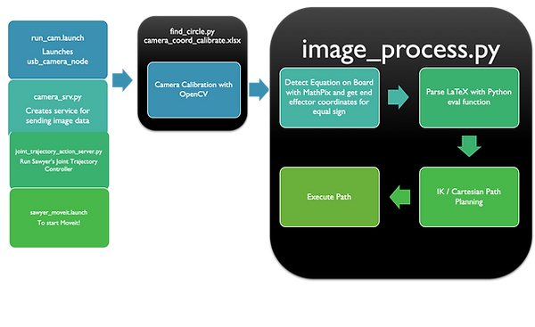
Our overall control flow consists of the following steps: (1) computer vision sensing of human-provided input, i.e., a mathematical expression, (2) logic that interprets this input and converts it into robot path trajectories and coordinates, and (3) actuation based on the planning done in (2). Together, these steps allow us to solve and write a mathematical expression, be it a function on one independent variable or an arithmetic calculation, as the graph or the constant answer.
The design criteria for Sawyerarithmetic:
1. To recognize digits and operations consistently
2. To be able to compute/find paths to draw digits
We implemented the three parts of our control flow as follows:
(1) We used the Mathpix API to convert pictures of mathematical expressions into some Unicode equivalent. In particular, we chose the LaTeX output offered by the API due to its predictable formatting.
(2) We first used the Desmos graphing calculator to plan the trajectories that would correspond to specific digits. These trajectories became the paths we planned.
(3) The MoveIt Inverse Kinematics path planner then allowed us to actuate the trajectories.

Design Choices That Eventually Changed
Although our original design called for us to develop our own machine learning model for object recognition in equations/expressions, Python compatibility issues led us to consider the Mathpix API instead. Although this did not run into compatibility issues, it did come with a few problems. We now had to parse the output from Mathpix, and due to the limitations of that, we were constrained to writing equations on the board in the format of code rather than in the format used in the classroom, such as using double asterisks for exponents rather than writing a superscript number. Furthermore, although Web APIs allow for distributed computing techniques to come into play, therefore reducing hardware requirements necessary for our local system, this means that the system may be subject to more constraints, e.g., a stable Internet connection, budget constraints for API costs, etc.
We also had to implement path planning without constraints because constraints would lead to increased failures in finding a solution for MoveIt!'s Inverse Kinematics solver, or sometimes wouldn’t find solutions at all. However, this occasionally led to Sawyer finding an awkward path that would lift the pen off the whiteboard.
To improve the ability for MoveIt’s IK solver to find solutions, we had to use Sawyer rather than Baxter for its better range of motion. In doing this, we sacrificed the better camera abilities of Baxter and had to use a webcam with Sawyer.

Implementation
Hardware
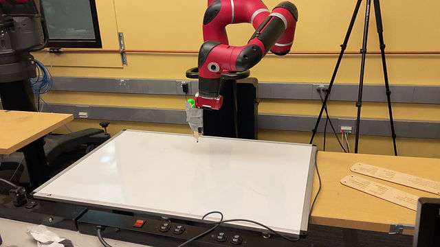
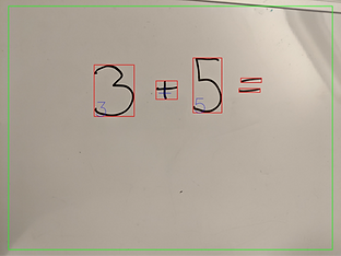
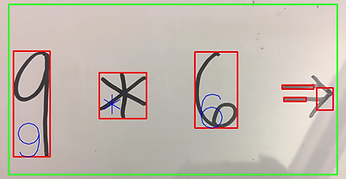
We utilized the Sawyer robot, and a USB camera. The webcam was used to scan the handwritten math expressions and to localize the location of the equal sign, while Sawyer was used to write the solutions to the math problems and to draw graphs.


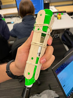
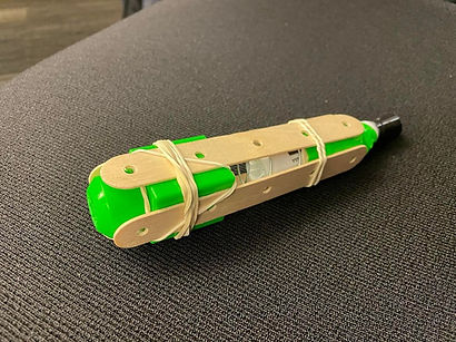
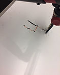
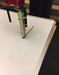
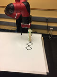
An interesting problem we solved was the actuation issue where the marker did not make contact with the whiteboard consistently which caused the robot to draw disconnected dots instead of smooth numbers. We solved this problem by attaching the expo marker to a home-made spring contraption using the spring from a notebook, popsicle sticks, and rubberbands. We fixed the contraption onto Ada’s gripper with duct tape.
Before (Red portion drawn by hand)


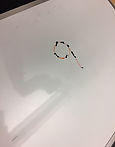
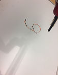
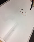

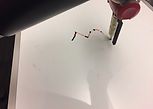

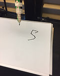
After (Completely drawn by Sawyer)


Software Rundown (Github Linked below)
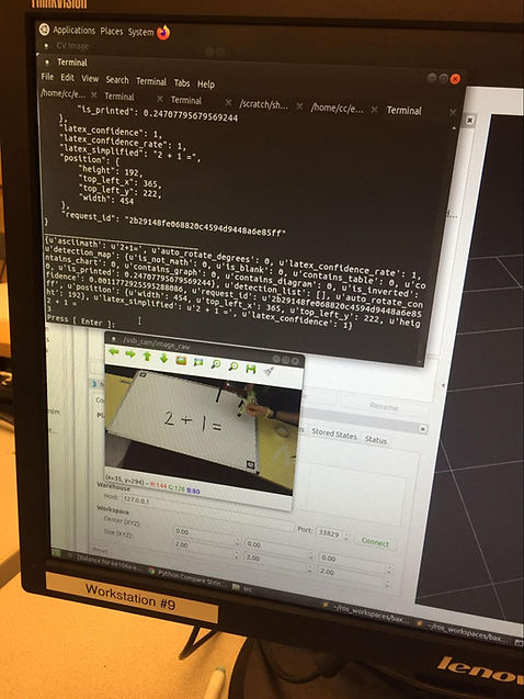
Sensing: Initially, the image_process.py file acts as a client, and prompts the server image_srv.py (which is subscribed to the /usb_cam/image_raw topic) for the last scene image seen from the USB camera, which is stored as a ROS image message. In more technical terms, image_srv.py fulfills the service last_image for image_process.py. This is then processed using CvBridge, which converts the ROS image message to a NumPy array, which is what MathPix takes in as input. MathPix then outputs a variety of data about the image, which includes a version of the image in Latex formatting. By parsing specifically the Latex output, we can determine whether it is a function to be graphed, or an equation to be evaluated. We then grab the important portions of the output (digits, operators, etc.), and format them in such a way that we can use Python’s eval function to evaluate the result, or so that we can replace variables with numbers so that we can evaluate points along which we then graph.
Planning/Actuation: Both have methods of generating a series of points to define the path Sawyer has to take using equations and the generated points are run into MoveIt’s IK solver to find a path for Sawyer to take. Initially, Tf_echo was used to find points in a trajectory that created a zero when Sawyer’s arm was moved around manually in zero-g mode. This solution was not ideal because it fixed the numbers to a particular spot on the board and the zero was not symmetrical when actuated. Moreover, Sawyer would often fail at finding a solution through the points found through moving the arm and increasing resolution with more points was difficult. To improve upon this, the path of the numbers were customly designed with piecewise functions that could be shifted across the board to the location of an equal sign. This idea started with the equation of an oval for a zero.
Moreover, a coordinate transformation had to be done from the reference frame of the cartesian coordinates to the reference frame of the end effector so that the solution could be written facing up towards the user. In particular, the coordinates had to be rotated 90 degrees counterclockwise to be written upright on the board, which was accomplished by setting the x value of the end-effector equal to -y and the y value of the end-effector equal to x. Resolution to make smoother curves could be improved by increasing the number of x values in the specified range of x values inputted into the equations. All numbers are written relative to values specified as x_center and y_center and have been designed to be aligned on the same line. Using these relative variables, consecutive numbers are written by incrementing the starting y_center value, which is the location of the equal sign, by the particular width of the number. Each generated point is run through MoveIt!’s IK Solver to move Sawyer to the specified point, where a higher number of points is used to get smoother curves. As for the graphs, the origin of the graph can be specified within the limitations of Sawyer’s range of motion and the window size of the graph can be adjusted. The center of the window frame can also be moved from (0,0). Generated values greater than the specified window size are thrown out to ensure Sawyer only graphs points within the square window size. In order to translate graphs onto the whiteboard, a calculation was done in which the values generated by equations were scaled down by a factor found by dividing the window size by the whiteboard’s vertical board length. The generated points also had to be rotated 90 degrees counterclockwise to get the correct orientation of the graph facing upright towards the user by setting the x value of the end-effector equal to -y and the y value of the end-effector equal to x. The bounds of the whiteboard were inputted as a variable, and as a result the system is robust in the way that it will not write off the whiteboard if it runs out of whiteboard space. This functionality is seen in the way Sawyer moves along the board without touching it to indicate that the points it was given to graph go off the board. This functionality was kept in where it moves along the board in order to account for cases where a function may move off the board for a bit and then moves back when it crosses the x-axis for a second time. This functionality also enables the flexibility to move the origin around to any spot without worrying about the marker drawing off the board. Again, each generated point is run through MoveIt!’s IK Solver to move Sawyer to the specified point, where a higher number of points is used to get smoother curves.
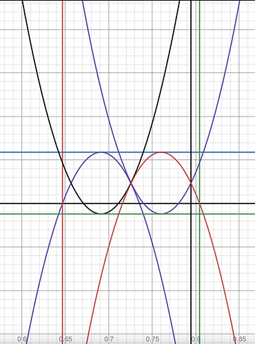
Graphs used to generate digits:
Results
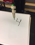
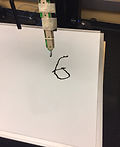
Sawyerarithmetic was able to recognize integers, basic operators, and an equals sign (and its position) using the attached camera, and then write the result of the equation next to the equals sign.
Sawyerarithmetic was also able to recognize functions and graph them on the whiteboard. The extent of functions able to be graphed were those supported by Python’s eval function, meaning that the format generally has to be that of a polynomial.
Conclusion
Through this project, we applied course concepts on Computer Vision (object recognition + segmentation), Inverse and Forward Kinematics, Coordinate Frame Transformations, and Path Planning. This project also gave us a first hand taste of engineering in practice and we were able to find solutions to multiple problems that arose in the process.
In terms of final results, we surpassed what we set out to do initially. Instead of just integer math, we also incorporated graphing functions. Of course, this didn't come without challenge, and there's definitely room for improvement.
For this project, we had initially set out to work on the vision and motion planning and actuation part in two separate teams. On the vision part, there were issues concerning Python and Tensorflow compatibility on the Cory 105 lab computers, difficulties with finding an angle where the camera could read the board and not distort the image for purposes of accurately translating camera coordinates to end effector coordinates, and issues with collecting and annotating enough data to train a model to accurately detect numbers. Initially we had found a pre-trained model on a public repository, but after testing it, we saw that we would need to implement our own model to get more accurate mathematical equation detection. We tried to implement a model with transfer learning on MobileNet, but issues concerning Tensorflow compatibility with the M1 Chip made this difficult to accomplish. Then, a model using a HOG and SVM detector was trained on our own manually annotated dataset, but not enough data was collected to produce accurate results. On our third iteration, we had a Tensorflow model trained on a Kaggle dataset that had the limited capabilities of detecting a single digit and operation. This model also did not work with Python 3.5 on the Cory 105 lab computers, because the latest version of Tensorflow was not supported.
We ended up using Mathpix, which came with its own advantages of being able to perform multi-operational mathematical expression detection while also having a difficult LaTex output that required us to write code to parse the output to perform computations. We had initially planned to use SymPy to parse the output, but there were compatibility issues with this for the Cory 105 lab computers and this is why we needed to write code to parse the data. We first tried to use a library for converting latex into Sympy called latex2sympy, but this led to issues with installation on the lab computers. We then tried using Python’s Re library for regular expression matching, but this constrained our expressions to expressions of a particular format. To give the ultimate flexibility, we used Python’s eval function on the string given by Mathpix and the Re library’s sub function was used to replace the x in the string for equations with actual values before running the eval function.
Once we were able to successfully detect mathematical expressions, the next task on the computer vision side was to perform a camera frame to end effector translation. We needed to either consider eye-in-hand or eye-to-hand for calibration. Because eye-in-hand is the more accurate of the two, we initially had tried to use the Sawyer camera for reading equations, but found the resolution of the camera to be too low for being able to detect equations and AR tags on the board. We decided to instead use a webcam and we were unable to attach this webcam safely to the end effector of the robot, which meant we would be using the method of eye-to-hand for camera calibration. Because of this, we needed to work towards accuracy and carefully make design choices that would minimize error for the translation of camera coordinates to end effector coordinates. We had initially tried to translate coordinates with AR Tags on Moveit but found that the AR Tag positioning was not going to be as accurate as we might expect. As an attempt to achieve more accuracy than can be obtained through MoveIt, we made our own custom method of camera calibration using OpenCV which involved thresholding for the white board and black AR Tag squares to find the coordinates of these points of interest. We then would move the end effector to these spots and record the x and y coordinates. We would develop an equation that would translate camera coordinates to end effector coordinates with a polynomial of best fit through these points. There was much human error from manually moving the end effector to the center of the squares and it was difficult to know whether the end effector was actually at the center of a square. Furthermore, the angle of the camera to the board was distorting coordinates. To improve on this design, we modified the OpenCV thresholding and contour detection to find the camera coordinates of dots that Sawyer would place on the board with an expo marker rather than record the center of AR Tags. Four dots were made with programmed end effector positions. We also repositioned the camera to make it more parallel to the board to minimize the effects of distortion along the y camera axis. From this part of the project, it was helpful to have someone who worked on both the computer vision and kinematics side of things because it helped inform that the translation of the camera coordinates for the y axis of the camera frame corresponded to the x-axis on the end effector frame for purposes of fitting the points on a polynomial curve, but alternatively a rotation operation could have been performed. Through these corrections, we were able to get a more accurate camera frame to end effector coordinates so that our end effector could write numbers to the right of an equal sign that was detected on the board.
On the actuation and planning side of the project, we had struggled with finding a good range of the end effector to write digits. While choosing Sawyer gave us a better range of motion for the end effector in comparison to the Baxter bots, there were still limitations to where Sawyer could reach, so it was important to define a set of reachable positions for Sawyer for positioning our whiteboard. Initially, we had manually moved the robotic arm and hard coded positions, but we were not satisfied with the first zero we wrote. The robot would lift the arm in between positions so we needed to get a smaller step size. As a result, we looked into path tracing with mathematical equations and were able to write digits 0-9 in this way. However, there were issues concerning marker contact on the board when Sawyer was writing. To resolve this issue, we built a spring contraption that would allow Sawyer some more flexibility with making contact with the board and this allowed marker strokes to be drawn on the board.
Possible future Improvements
Occasionally when Sawyer starts in an awkward starting configuration, it will find a path that involves it lifting off the whiteboard and spinning a joint to an unwanted configuration. Although we tried solving this by adding constraints, this would lead to Sawyer having difficulty finding paths, so we just ensured that Sawyer would start in a similar configuration every time. Ideally, we could start Sawyer in any configuration and it wouldn’t cause problems.
Sawyer also has issues with running out of whiteboard reachable end effector space for larger numbers and we would like to implement a feature to have Sawyer continue writing on the next line when it runs out of space.
We would also like to implement more fonts for numbers by having a computer vision component that can take images and create a trajectory from them.
We would also try to incorporate a better system of parsing, so that we could include functions that Mathpix does not convert well as a string like writing np.cos(x) on a board. If Mathpix directly translated this as np.cos(x), Python’s eval function could be used to solve these more complex equations.
Improvements Since Live Demo/Presentation
We now are able to detect an equals sign, and write the result of the equation at the equals sign.
We used compute_cartesian_path from MoveIt! to smooth out the curves drawn. Video below for drawing a sin function using the cartesian controller:

Tensorflow model images: